Documentation
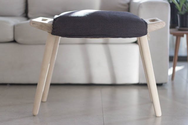
AP29 "Papa Bear Chair" Ottoman | Hans Wegner
.
Although not as well documented as Hans Wegner's other pieces, there is enough information on it to get rough dimensions and angles.
The three elements of the ottoman are the legs, the handles and the seat. The legs and handles are visible but the timber of the seat is not. The seat was therefore made with some leftover plywood, and the rest were made of nicer solid wood, in this case, Kauri Pine.
 |
| The handle pieces (Kauri Pine) connected to the seat (plywood) |
Firstly, two large blocks of plywood were made. 4 sheets of 12mm plywood each were cut. Their dimensions had to be large enough to make the front and back ends of the seat. These cut sheets were then stuck together with a generous amount of wood glue and clamped together for a couple hours for the glue to dry and strengthen properly.
Next, the side profile of the seat was traced onto the blocks of plywood and cut to shape with a bandsaw.
In order for the planks to sit onto these pieces, grooves had to be cut along the inner edges so that they would flush. A table router was used to do this, with the curve as the guide for the bearing and the router bit set to cut about 10mm. This was the highest that it would go.
Because the plywood used was 12mm thick, a 10mm recess would mean that the planks sitting on it would not sit flush. The planks were cut from the remaining plywood and then using the same table router, about 2mm was routed out at their edges.
A dry test to see if the planks nicely fit the end pieces revealed that the planks went over the edge. One plank was trimmed down to get rid of the excess and they were then glued and nailed into the end pieces.
While waiting for the glue to dry, the legs were turned. The top and bottom ends of the legs measure 40mm and 30mm in diameter respectively. The tapering of the legs took a while. A straight edge was frequently used to check if the tapered legs were straight.
After achieving the best shape the gouges could do, the legs were then sanded down to remove any difficult bumps and to get a nice smooth finish.
Next were the handle pieces. The side profile of the handles were traced onto the timber. Lengths and angles were measured and a table saw was used to remove some of the material on one side.
The rest of the wood was then shaped with a scraper shave and hand plane.
Measurements for the handles were marked out and holes were made using the drill press. A jigsaw was then used to cut out the rest of the handles.
To round the edges of the handles, a hand router with fillet bit was used. However, this left uneven edges and a few burn marks. An orbital sander was used to deal with that.
Holes needed to be drilled into the handle pieces for the legs to slot into. Because the drill press could only drill vertically downwards, a jigs had to be made. First, the drill press platform was propped up with a shim in one direction. This ensured that the drill would go in perpendicular to the tangent of the curve, allowing the legs to angle outwards.
However, the legs also angle in the other direction. A box was made to stabilise the handle piece and another shim propped it to the right angle. Now, the drill press was all set up, with the platform angled in one direction and the box sitting on it, angling the handle piece in the other direction.
 |
| Handle piece clamped down with a test piece. The holes which the legs slot into look like the "stepped" hole on the left. |
The seat and handle pieces were then joined with dominoes and wood glue.
Using a template, the curve of the seat was marked and shaped with a bandsaw and disc sander. The rest of the sharp edges were then filleted with a hand router and sanded smooth.
The legs went on.
lightweight wadding was stuffed into upholstery fabric. drawstring channels were stitched on the sides and strings were put through. In hindsight, using high density foam instead of wadding could have been better. That way, the seat would not be as puffy.
Thorncrown Chapel | Euine Fay Jones
.
With the help of the workshop staff, the edges of the base pieces were mitred for clean edges. They were then sanded and glued together. The sharp edges were broken so they would feel nicer.
 |
| Edge (bottom) broken/cleaned up |
The small intricate pieces were then laser cut and sanded to remove the burn marks. Spares were also cut, which were ultimately used as some broke in the process.
The pieces were then glued together with white PVA glue. They were secured into position with tape and weights. Straight blocks were also used to ensure they were glued on straight.
Next, the terrain was laser cut, sanded and glued together with white PVA glue.
The two roof sheets were then mitred at the joint edges and glued to the timber frame.
Although precautions were taken to ensure the pieces were glued on as straight as possible, some pieces still did not sit exactly where they were supposed to. This became apparent when the frame was glued onto the base.
Warping was also another problem. The frame did not warp as the pieces were glued together and its rigidity came from that. The end pieces however did not fare so well.
Azuma House | Tadao Ando
.
After modelling the house in SketchUp, the negative spaces were easily modeled as well. These negative spaces were to be made of blue foam.
The first attempt to cut most of the negative space as one piece failed because the inner corners would burn up and end up in a mess.
The second attempt to cut the negative spaces as separate cuboids and join them together was better. There were no corners that could burn up, just simple straight cuts. However, the wire on the hot wire cutter was not completely vertical and the minute difference in angle snowballed over the many pieces, creating incorrect gaps and angles.
After checking that the hot wire was as vertical as possible, the third attempt went well. Instead of using PVA glue to join the foam like for the second attempt, I used double sided tape instead. This eliminated the voids and air pockets that the squeeze out could create during casting.
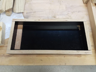
An enclosure was made out of form ply and the model was cast with Ultracal 30, a strong gymsum cement. It was left to cure for 2 days before being released from the enclosure and had foam taken out.
 |
| A piece on the right chipped off when removing the foam |
The edges were then sanded smooth.


Comments
Post a Comment